Fixing the Cassegrain Mount
Well, after much work on the optics, it's time to fix the mount for the
Cassegrain.
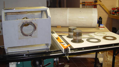
The old declination bearings were just plain worn out.
Here's
a picture of the tube cradle, tube, and the old declination bearings
after
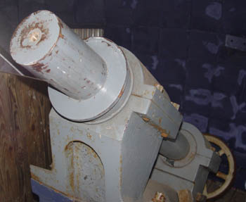
disassembly. A picture of the massive right ascention shaft is
shown
next.
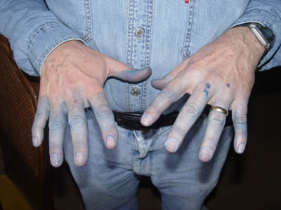
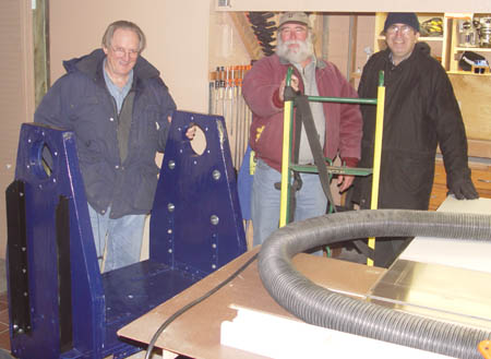
Mike Conron took the tube cradle and the fork to his garage for
cleaning,
sanding, and a new navy blue paint job. The cleanliness of his
hands
was sacrificed so that the wooden scope parts would be protected from
the
elements, as shown in the next photo. Then the "movers" pictured
brought
the fork into my basement for further work.
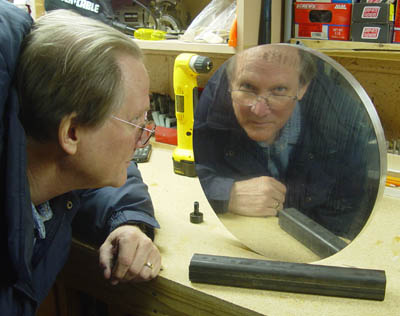
I obtained two 14 3/4" diameter by 1" thick aluminum disks from S&S Machine
in California for a very reasonable price. They are machined
round,
and the faces are polished, as shown in the next picture. (No,
the
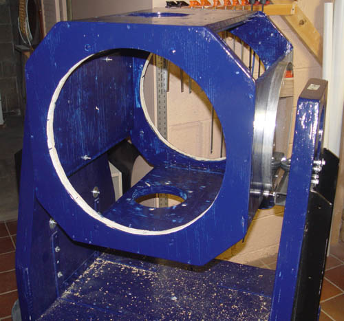
reflection did not break the disks.) These were then bolted to
the
newly-painted tube cradle, which sits on rollers in the fork mount
(next
photo). Great care was taken to make sure the disks were
concentric
and as parallel as I could get them.
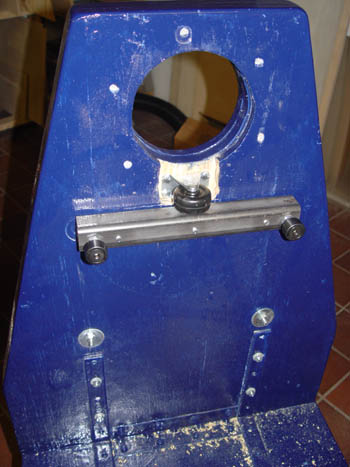
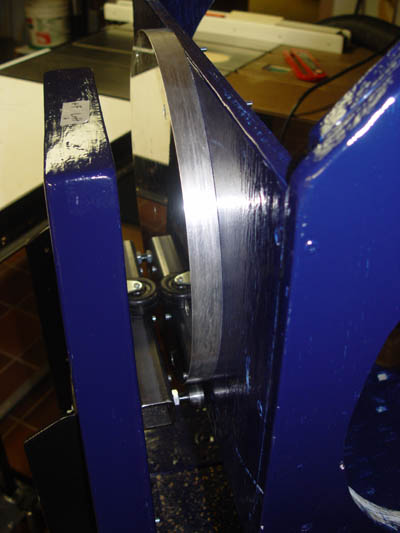
The next two pictures show the rollers and caster which constrain the
movement
of the aluminum disks. The rollers are mounted to 1.5" square
steel
tubing (3/16" thick wall) on the inside of each of the fork arms.
The
rollers bear the vertical load, and the casters support the lateral
load
which is at a maximum when the scope is pointed to the east or west.
The
second picture is a closeup of the disks and rollers together.
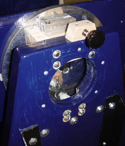
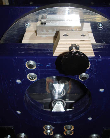
After this, I made the two "keeper" assemblies that make sure the disks
stay
seated on the two lower rollers. These were simply two bearing
assemblies
that attached to the center of each disk. One utilized a 5/8"
bearing
with a 5/8" aluminum cylinder inside the bearing that was bolted to one
of
the disks. The other bearing was a 1" diameter aluminum cylinder,
bolted
to the other disk, with a piece of nylon, cut out to match the 1"
cylinder,
which constrains movement. Both bearings were attached to the
fork
using pieces of plywood (Baltic Birch). This permits a slight
amount
of "give" if the center holes in the disks are off slightly. I
also
added a device to vary the friction of the declination motion.
Here's a closeup of one of the bearings and the friction adjustment.
The result is that the declination axis motion is very smooth, and most
of
the physical construction on the telescope is done. Now we need
to
drill the new mounting holes in the tube for the mirror cell and one
fan,
paint the new parts and touch up the fork and cradle, install fans, and
reassemble.


