January 16,
2011: An
example of deceptive interferometry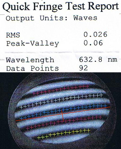
I really just can't believe some of the stuff that I see.
This one certainly made me shake my head.
The test report at right was sent to me by a rather disgusted client.
I tested the same flat on one of my reference flats and saw a very
similar image.
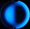
Let's
look at the image. Note the placement of the "+" signs -
these
are points tracking the dark center of the fringes (it is also possible
to trace light fringes).
Note how the "+" signs do not go all
the way to the edge of the mirror. This means that the
accuracies
given in the report do not take into account the outer portion of the
mirror, where the fringes continue to curve downward.
It is also
possible to observe the non-uniform fringe spacing in this image - the
fringes are spaced more closely together at the top of the test image
than the bottom.
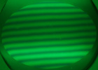
Overall, this mirror is convex. Along the
major axis, trace the red line from one end of the flat to the other.
At the center, I have drawn a perpendicular red line from the
center of one fringe to the center of the next fringe. This
short
red line is one fringe long, corresponding to half a wave on the glass.
The long line intersects the short one very close to 1/3
of the way from the end of the short line (in the center of the same
fringe). This means that the departure from flatness is 1/3 *
1/2
wave = 1/6 wave (0.17 wave) on the glass.
Thus, the total error
on the major axis is about three times the Peak-Valley error indicated
on the report, which was apparently done with a Zygo interferometer.
A well
calibrated interferometer may not lie, but leaving out a portion of the
mirror can certainly make the numbers look a hell of a lot better!
The moral here? Results from an interferometer are only as
honest as the optician/supplier allows them to be.
Please check back for future installements of "In
the Shop".
Mike
Lockwood
Lockwood Custom Optics